![]()
The Cassini Imaging Science Subsystem consists of two cameras : the Narrow Angle Camera (NAC) and the Wide Angle Camera (WAC) (see Figure 1-1 and Figure 1-2, respectively). Environmental and calibration testing of the NAC and WAC flight model (FM) cameras were performed at JPL's Environmental Test Laboratory from January to August of 1996. Each camera was tested individually, which precluded utilizing the simultaneous imaging mode. The evaluation of the data taken during this subsystem level thermal vacuum test is discussed in this report, as is the component level test results. Additionally, some limited testing was performed on the stacked spacecraft during Spacecraft Solar Thermal Vacuum (STV) testing, where the simultaneous imaging mode was used. Dark Current data from the STV test is discussed in Section 5.1.5.
This report is broken out into six main sections :
1) Anomalous Test Data - discusses unexpected and/or anomalous results ;
2) Calibration Equipment - describes the equipment and conditions used for calibration testing ;
3) Component Calibrations - discusses results of testing performed at the component level prior to subsystem level integration ;
4) Subsystem Calibration - discusses results of the test data performed at the subsystem level during thermal vacuum testing ;
5) In-Flight Data Acquisition Recommendations and Guidelines - compiles a list of recommendations from a "lessons learned" point-of-view.
6) Radiometric Calibration Steps - includes the sequence of steps required in order to radiometrically calibrate the images.
The appendices of this report consist of the following information :
| Appendix A - | Test Results Summary |
| Appendix B - | Dependent Parameters Summary |
| Appendix C - | Released Reports Log (JPL and Science) |
| Appendix D - | Applicable ISS Documents Log |
| Appendix E - | Archived Data (CD ROM archive description, CD ROM logs, electronic data files log with downloadable electronic data files) |
| Appendix F - | Compiled Data Tables |
| Appendix G - | Science Team and Other Calibration Reports |
Below is a brief description of the cameras :
Optics - The NAC optics consist of a Ritchey Chretien configuration with a focal length of 2000 mm, a spectral range of 200 - 1100 nm, and a field of view of 0.35 x 0.35 degrees. The WAC optics consist of the inherited wide angle optics flight spare from Voyager (with a new set of field elements) which is a refractor design with a 200 mm focal length, a spectral range of 380 - 1100 nm, and a field of view of 3.5 x 3.5 degrees. The inherited WAC optics contain a calibration lamp.
Electronics - Both the NAC and WAC share the same electronics design which are broken out into two main areas : the Sensor Head Electronics (SHE) and the Main Electronics Assembly (MEA). The SHE consists of the signal chain electronics and the clock drive electronics, and is part of the camera head located on the Remote Sensing Pallette. The MEA is located in Bay 12 of the spacecraft and contains the following electronics : CCE - Camera Control Electronics / Lossy Electronics, MDE - Mechanism Drive Electronics, and the PSE - Power Supply Electronics. The CCE provides the electronic connections and interfaces between the ISS Engineering Flight Computer (EFC) and the rest of the ISS subsystem electronics. The MDE generates electronic signals for the operation of the filter wheel assembly, the shutter assembly, the calibration lamp (WAC only), and the floodlight lamps. The PSE (power converter unit) interfaces with the 30V spacecraft bus via the solid-state switch in order to provide the required ISS voltages and currents.
Charge Coupled Device (CCD) - Both cameras have a 1024 x 1024 pixel array CCD which was manufactured by Loral and packaged by JPL. Pixel size is 12 x 12 microns. The CCD is coated with Lumogen to enhance the UV response. During camera operation, the CCD is radiatively cooled to -90 °C in order to suppress dark current and the effects of ionizing radiation.
Lightflood - Six TIL24 infrared light-emitting diodes (LEDs) provide the lightflood to the CCD during the Prepare Cycle of an image sequence. The duration of the lightflood is programmable with the current default being 200 msec.
Data Conversion - 12-bit data can be converted to 8-bit data by either using a 12-8 conversion table (see Appendix F) or by using the 8 least significant bits (8-LSB).
Data Compression - Two types of data compression are available : lossless (Data Compression Chip) and lossy (COFO and DCT chips from MATRA). The normal (no compression) and lossless compression modes use both the 12-bit and 8-bit data sizes (12-bit, 12-8, or 8-LSB) ; the lossy compression mode must be used with either the 12-8 or 8-LSB data conversion modes (the lossy chips can only except 8 bits of data).
Summation Modes And Gain States - The following summation modes and gain states are available :
|
|
|
|
|
|
|
|
|
|
|
|
|
|
|
|
|
|
|
|
Imaging Modes - The NAC and WAC cameras can be commanded to take simultaneous images (where both cameras shutter together), or can be commanded to take images individually.
Filters, Filter Wheels - Each camera has a filter wheel assembly consisting of two filter wheels. The two NAC filter wheels hold 12 filters each, for a total of 24 filters. The two WAC filter wheels hold 9 filters each, for a total of 18 filters. Each filter wheel is driven by an independent motor, and can be moved in either the forward or backward directions at a rotational speed of 2 filter positions per second. Normal image operation would have the flight software determine the shortest path to the specified filter combination. Sensors detect the "Home" position of the filter wheels (position 1), which is the position which holds the clear filter.
Shutter Assembly - The shutter assembly contains two blades : Blade A and Blade B (see Figure 1-3). During the Prepare Cycle of an image sequence, the blades are set to the "Reset" position, if not already in that location. The movement of Blade A to the "Activate" position initiates the exposure; the movement of Blade B to the "Activate" position completes the exposure. At the completion of the image sequence, the blades remain in the "Activate" position. Exposure durations can be selected from a 64 item exposure index table which includes the following options : bias frame (0 second integration time), exposure times from 5 msec to 20 minutes, and a "no operation" mode.

Figure 1-1 - Narrow Angle Camera (NAC) Flight Model Camera Head Assembly (CHA)

Figure 1-2 - Wide Angle Camera (WAC) Flight Model Camera Head Assembly (CHA)
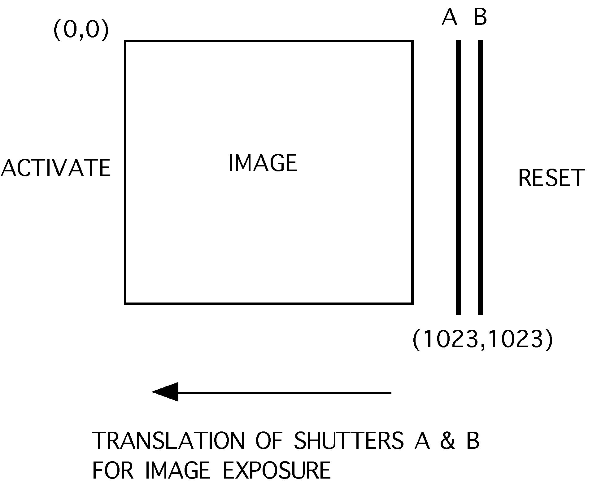
Figure 1-3- Shutter Movement with Respect to Image
![]()
![]()