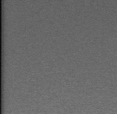
Figure 2.1-1 - NAC Dark Frame Exhibiting the Dark Band

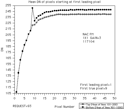
Figure 2.1-2 - Dark Band Profile
Reference 2.1-1 - "Cassini ISS Gray Bar Artifact Review Team Report", dated March 06, 1997, authored by D. Norris
During flight calibration testing, a dark band along the left side of the image was observed for the bias frame (0 exposure) images of the NAC FM. The dark band was visually noticeable anywhere from 1-12 columns wide. No observation of this dark band was made for the WAC FM. The dark band can be seen in Figure 2.1-1. Figure 2.1-2 provides an example of the dark band profile.
A review team was formed to determine the cause and impact of the dark band problem. A brief summary of the results of the review (Reference 2.1-1) is listed below.
1) The Cause : Trouble-shooting the dark band anomaly isolated the problem to a high resistance between the CCD and ground. This high resistance has been traced to the interface of the aluminum and the silver-filled epoxy, which bonds the CCD to the gold-coated ceramic header. Tests showed that a dark band may be formed by heating the CCD. It was also noted that if no dark band is observed at room temperature and the CCD is not heated, it is unlikely that a dark band will form.
The role of elevated temperature to the formation of the dark band is theorized as this : when the CCD is heated, water vapor from the silver-filled epoxy pushes to the interface surface (the epoxy layer is between the CCD aluminum and the gold ground contact). An increase of interface resistance is formed with the increased amount of humidity and the elevated temperature at the interface surface. Also, the humidity is a factor in the formation of an oxide layer on the aluminum, also increasing interface resistance.
Testing also showed that applying a higher than nominal voltage could "zap"(break down barrier resistance when sufficient voltage is supplied) the resistance back to nominal levels.
2) The Recommendation : Use the hardware as is. The risk of making a hardware change (e.g., a zapping circuit) outweighs the risk of dealing with the dark band as anomalous data (clipping dark band portion of data). Also, the possibility exists that the performance will improve after the CCDs are cooled over long periods of time in space. For the future : do not use silver-filled epoxy and aluminum to make an ohmic contact.
Calibration note : The dark band anomaly can be found in the bias frame data by looking for a difference between the overclock and extended pixels values. The dark band is only seen in the offset files, not in the radiometric slope files.

Figure 2.1-1 - NAC Dark Frame Exhibiting the Dark Band

Figure 2.1-2 - Dark Band Profile